Product Overview
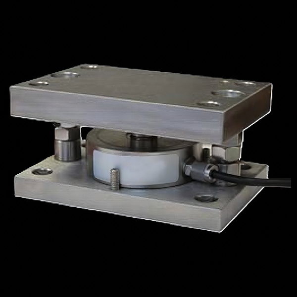
WIKA-ST (tecsis) SLM weighing modules turn a hopper, silo, vessel, or platform into a scale: each module is a stainless load cell + self-leveling mount that goes under a support leg, and three or four of them under the vessel read its live weight. The spherical rocker pin is the point — it keeps the cell vertically loaded while the vessel breathes, so accuracy (≤±0.05% FS through 5 t) survives thermal growth, piping forces, and imperfect installation. 0.25 to 28 t per module, IP67, 150% safe / 250% lateral load limits, hold-down screws that double as cell-replacement jacks, and a 2-wire hazardous-location wiring option. Sold as a matched module set, summed in a junction box to one mV/V output.
Key Features & Benefits
- Self-leveling is the accuracy feature — a rigid cell under a vessel reads whatever thermal growth, piping push, and imperfect steel feed it — the SLM’s spherical rocker pin re-aligns the load path on every disturbance so the cell only ever sees vertical weight. The datasheet’s phrase: it measures “even if the conditions aren’t perfect.” Built for real tank farms, not lab frames.
- A weigh module, not a parts list — cell, rocker, bearings, plates, hold-down screws, and ground bonding arrive as one engineered assembly — the corner of a vessel-weighing system in a box, three or four of which make the scale. The engineering is in the module so it is not on your drawing board.
- Swap the cell without lifting the vessel — the four M12 hold-down screws double as jacking bolts: lock the top plate at dimension E, lift it off the cell, and replace the cell with the vessel standing full — the maintenance move that keeps a process tank in service. Cell replacement is a wrench job, not a crane job.
- Rated for the sideways world — a 250% FS lateral load limit plus a controlled 3-mm horizontal float means thermal expansion, agitator torque, and a bumped platform stay inside the design instead of shearing gauges. The side loads are in the spec, not in the failure report.
- Precision that earns dosing duty — ≤±0.05% FS accuracy with ≤±0.02% creep on the popular sizes is batching-and-dosing grade — the vessel scale can close the loop on ingredient addition, not just inventory. Accurate enough to charge the batch by.
Specifications
- Operating principle
- A complete compression weigh module: a stainless top plate and base plate housing a tecsis load cell, with a spherical rocker pin riding between bearings on top of the cell. As the vessel expands, contracts, or sits slightly out of true, the rocker keeps the cell loaded vertically — the strain gauges read weight, not side force.
- Capacity / measuring range
- 0.25 / 0.5 / 1 / 2 / 3.5 / 5 / 10 / 15 / 28 t per module; compression systems use three, four, or more modules under the vessel.
- Accuracy & repeatability
- ≤±0.05% FS through 5 t; ≤±0.10% FS at 10–28 t. Creep (30 min) ≤±0.02% FS (≤±0.05% on 15/28 t); zero balance ±1% FSO.
- Output & excitation
- 2.0 ±0.01 mV/V full-bridge; excitation 10–12 VDC (15 VDC max); 1,140-Ω input / 1,050-Ω output bridge; integral 6-m, 5-mm cable (4-wire; 2-wire hazardous-location wiring option). Multiple modules sum in a junction box to a single output.
- Overload & breaking force
- Safe load limit 150% FS; lateral load limit 250% FS.
- Body material
- All-stainless construction — plates, mount, and cell.
- Sealing & protection class
- IP67 (load cell).
- Dimensions / fit
- Footprints from 150 × 100 mm (0.25–1 t) to 230 × 180 mm (10–28 t); installed stack height (“dimension E”) 80–165 mm by size.
- Mounting / load introduction
- Bolts to a concrete floor or steel plate (welding allowed — with the cell removed first). Four M12 screws with jam nuts tie the plates, set the installed height, act as jacking bolts for cell replacement in place, and the correctly installed module keeps 3 mm of free horizontal float. An M6 ground screw and cable bond the plates for a defined ground path.
- Temperature range
- −30 to +70°C. Thermal effects ±0.02% FS/10°C zero and span (±0.03/0.04% on 15/28 t).
- Approvals & options
- 1-year tecsis LP warranty; hazardous-location 2-wire wiring option (no agency Ex mark is printed on the sheet — classified installs are an application review).
- Calibration & traceability
- Cell and mount ship as a matched pair (cell 99-5134-XXXX in mount 99-5135-XXXX); do not shorten the integral cable — trimming it changes the calibrated output.
- Build & lead time
- Sized per module load (vessel weight + contents, divided by the mount count, with headroom); quoted as a module set. Quote-only, no public price list.
Common Applications
- Hopper, silo, and vessel weighing
- Platform scales
- Batching and dosing by vessel weight — closing the loop on ingredient addition
- Inventory monitoring on storage tanks and silos
Design & Selection Considerations
- Design the whole load path, not just the modules — compression weighing works when ALL the vessel’s weight goes through the modules: every pipe must connect flexibly, the mounting surface must be level within ±0.5°, and all mounts must sit coplanar so they share load. A single rigid pipe is a hidden bypass that steals weight. The piping drawing is part of the scale.
- Install with a dummy cell, lower the vessel gently — the manual is explicit: build the mounts with the load cell removed (or a dummy in its place), and lower the vessel with extreme care — a multi-ton vessel dropped even a fraction of an inch can kill a cell before the scale ever reads. The riskiest moment in the system’s life is installation day.
- Water is the quiet enemy — provide drainage and a drip loop; standing water at the mount damages the sensor over time even at IP67. Outdoor and washdown installs should be detailed for runoff. Design the puddle away.
- Never shorten the cable — the integral 6-m cable is part of the calibration — cutting it changes the output. Coil the excess and run it in flexible conduit if it needs protection; sum multiple modules in a junction box. Calibration lives partly in the copper.
- Welding near the module has a rule — bolting down is standard, and welding the base is allowed — but only with the load cell removed, because welder heat (and current) through the cell destroys it. Pull the cell before striking an arc.
- Size per module, count per vessel — divide vessel + contents by the number of mounts, then leave headroom for uneven distribution and surge — and remember the asymmetric base plate: alignment of the plates and the bearing locating hole matters at installation. Use the input form to send the vessel weight, leg count, and layout — we size the set.
To spec the right WIKA-ST weighing module set:
To configure the right WIKA-ST force sensor, have these ready: the capacity (and the worst-case peak load); whether the force is tension, compression, or both; how the load is introduced (through an existing pin, a ring in the force path, or a threaded line); the output you need (4–20 mA, 0–10 V, mV/V, CANopen, or wireless) and the cable run; the environment (temperature, washdown, classified area); any certification (ATEX/IECEx, functional safety); and, for a load pin, the existing pin dimensions to match. A legacy tecsis part number is fine — send it and we cross-reference the current WIKA-ST equivalent.
Force & Pressure Application Sheet ›Talk to an engineer directly — Scott Prater, Principal · 917-580-0878 · scott@pratertechnical.com
Specifications compiled by Prater Technical Partners from WIKA product datasheets.