Product Overview
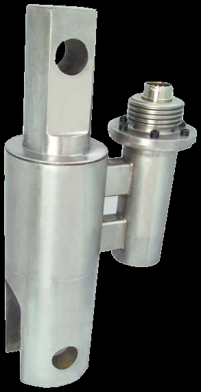
Well-service load cells put the force measurement on the moving parts of the well: the XLDR polished-rod cell (30,000–50,000 lb, 50-million-cycle fatigue life) drives pump-off control on rod-pumped wells; the coiled-tubing cell reads insertion tension and compression to 500,000 lb with an intrinsically-safe 4–20 mA output; and the wireline/slickline cell hangs in the line to 40,000 lb with a field-replaceable amplifier. All three are WIKA-ST (legacy tecsis) well-service builds — brochure summaries here, full datasheets with the quote.
Key Features & Benefits
- A fatigue life measured in strokes, not months — the XLDR’s 50-million-cycle rating exists because a rod-pumped well loads the cell on every stroke, around the clock — pump-off control only works if the sensor outlives the duty. The spec that matters is the one the pump jack writes.
- Serviceable where the service is remote — the wireline cell’s amplifier is field-replaceable and its shackle is integral, so a truck at a remote site swaps electronics instead of shipping the cell. Downtime measured in minutes at the wellhead.
- Intrinsically-safe signal off the wellsite iron — the coiled-tubing cell reads out as intrinsically-safe 2-wire 4–20 mA in fully welded stainless — a classified-area force signal with no separate barriers engineered per job. The classification travels with the cell.
Specifications
- Operating principle
- Strain-gauge load cells purpose-built for the three recurring well-site force measurements: XLDR rides the polished rod of a pumping unit for pump-off control; the coiled-tubing cell reads insertion tension and compression; the wireline/slickline cell hangs in the line with an integral tongue-and-yoke shackle.
- Capacity / measuring range
- XLDR polished-rod: 0–30,000 to 0–50,000 lb. Coiled-tubing: to 500,000 lb, tension and compression. Wireline/slickline: to 40,000 lb.
- Accuracy & repeatability
- XLDR: ±0.50% FSO. Coiled-tubing: ±0.20% FSO.
- Output & excitation
- Coiled-tubing: 4–20 mA 2-wire, intrinsically safe. Wireline/slickline: analog or digital output with a field-replaceable amplifier.
- Overload & breaking force
- XLDR: 200% safe overload. Coiled-tubing: 150% safe overload.
- Dynamic / fatigue rating
- XLDR: 50,000,000-cycle fatigue life — sized to the stroke-after-stroke duty of a rod-pumped well.
- Body material
- XLDR: lightweight cast-aluminum housing. Coiled-tubing: fully welded stainless steel. Wireline/slickline: all-welded stainless, hermetic construction.
- Mounting / load introduction
- XLDR clamps to the polished rod of the pumping unit; the coiled-tubing cell installs in the injector load path; the wireline cell hangs in-line via its integral tongue-and-yoke shackle.
- Approvals & options
- The coiled-tubing cell carries a CSA intrinsically-safe listing (per the brochure); confirm the approval for your classified area at order.
- Build & lead time
- These are brochure-level summaries — the full datasheet for the exact build comes with the quote. Configured per the capacity, the output, and the area classification. Quote-only, no public price list.
Common Applications
- Pump-off control — continuous polished-rod force on rod-pumped wells (XLDR)
- Coiled-tubing insertion force — tension and compression at the injector
- Wireline and slickline tension — well intervention, logging, and tool-retrieval monitoring
- Reservoir evaluation runs where line tension is the safety signal
Design & Selection Considerations
- Brochure numbers are the shortlist, not the order — these three cells are published at brochure depth — enough to pick the right family, not enough to configure a build. The full datasheet, ordering codes, and current approvals come back with the quote. Treat this page as selection, not specification.
- Get the load axial, centered, and free of side load — these transducers measure force introduced straight down their axis. Take an off-center or transverse load and the reading is wrong and the element can be damaged — the datasheets call for a load that is axial, centric, and free of transverse force and torque. Most field errors here are load-introduction errors, not sensor errors.
- Size so the working load lands in the upper part of the range — aim to put the routine working load high enough in the range for good resolution and signal-to-noise, with headroom for peaks. Oversize and resolution suffers; undersize and an overload event shifts the calibration. Use the input form to tell us the static load and the worst-case peak — not just the nominal.
- Know the gap between safe overload and breaking force — every unit has a safe overload it can see without losing calibration and a higher breaking force where it is destroyed. The danger zone is between them: a unit overloaded past safe but not to breaking keeps reporting plausible, wrong numbers. Any suspected overload should trigger a recalibration before you trust the data again.
- Watch cross-sensitivity where the load can swing off-axis — a side load produces a real, specified error (the F5301, for example, carries a cross-sensitivity rating for load applied at 90°). Where the loading geometry can move — a swinging sheave, a misaligned fixture — account for it in the error budget or constrain the geometry. Off-axis load is a spec line for a reason.
- Pick the output to match what is reading the sensor — a raw mV/V bridge needs a conditioning input (DAQ or indicator with a bridge card); an integrated or cable amplifier reads straight into a PLC as 4–20 mA or 0–10 V. Use 4–20 mA for long, noisy runs; 0–10 V for short test-bench runs. Decide it from the receiver and the cable distance.
- A legacy tecsis part number cross-references to a current WIKA-ST unit — the tecsis force line is now built under WIKA Sensor Technology. Use the input form to send the tecsis part number and we match the current WIKA-ST equivalent at the same spec, so a field replacement does not require re-engineering the installation. No need to re-spec from scratch on a like-for-like swap.
To spec the right WIKA-ST well-service load cell:
To configure the right WIKA-ST force sensor, have these ready: the capacity (and the worst-case peak load); whether the force is tension, compression, or both; how the load is introduced (through an existing pin, a ring in the force path, or a threaded line); the output you need (4–20 mA, 0–10 V, mV/V, CANopen, or wireless) and the cable run; the environment (temperature, washdown, classified area); any certification (ATEX/IECEx, functional safety); and, for a load pin, the existing pin dimensions to match. A legacy tecsis part number is fine — send it and we cross-reference the current WIKA-ST equivalent.
Force & Pressure Application Sheet ›Talk to an engineer directly — Scott Prater, Principal · 917-580-0878 · scott@pratertechnical.com
Specifications compiled by Prater Technical Partners from WIKA product datasheets.