Product Overview
A gearmotor is a Reuland motor integrally coupled to a gear reducer — the reducer trades motor speed for output torque at a fixed ratio, delivering high torque at low shaft speed in one compact unit with nothing to align. Reuland offers five reducer geometries (right-angle worm, helical-worm combination, helical-bevel right-angle, and helical parallel / concentric shaft) spanning ratios from 1.5:1 to 1800:1 and output torque to 350,000 in-lb, with the motor built in-house so the package can carry an integral brake, inverter or vector duty, a high-slip Design D, wound-rotor, or permanent-magnet input motor. Choose a gearmotor for a slow, heavy drive — pick the geometry by torque and shaft orientation, then size it to the duty.
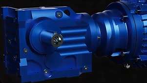
Key Features & Benefits
- High torque at low speed in one compact unit — the reducer turns motor speed into output torque at a fixed ratio, so a single matched package drives a slow, heavy load without a separate motor, coupling, and alignment job (the torque and ratio ranges are in the specifications). One unit to mount, nothing to align.
- A geometry for the shaft you need to turn — right-angle worm, helical-bevel right-angle, and in-line helical parallel/concentric geometries cover output shafts at a right angle or in line, flange- or foot-mounted, across a wide torque span. Pick the shaft orientation and the torque; the geometry follows.
- The motor is Reuland’s, so the options come built in — because the input motor is made in-house rather than bought, the build choices — inverter or vector duty, integral brake, Design D high-slip, wound rotor, or permanent magnet — are part of the unit rather than adapted onto a purchased motor. The motor features you want, engineered in, not adapted on.
- The motor comes off the reducer without a fight — years later the input motor still separates cleanly for service or replacement, where a plain shaft interface would have seized to the reducer — the patented coupling is what keeps that joint serviceable for the life of the unit. Serviceable in the field, not welded by corrosion.
- Built to order with no minimum quantity — engineered to the load — including non-standard ratios, frames, and motor builds — with a single purpose-built gearmotor as welcome as a production run. You are not forced into a catalog SKU or a minimum order.
Specifications
- Operating principle
- A gearmotor is a Reuland motor integrally coupled to a gear reducer: the reducer trades motor speed for output torque at a fixed ratio, delivering high torque at low shaft speed in one compact unit, with no separate coupling to align. A patented motor-shaft interface bushing joins the motor to the reducer — it resists fretting corrosion and lets the motor be removed from the reducer cleanly for service.
- Gear geometries & configurations
- Reuland builds the current line as three series — Series K (right-angle helical-bevel, 11 triple-reduction case sizes, ratios 8.0–160:1, multi-stage to 35,000:1), Series F (offset-parallel / helical shaft-mount, 9 double-reduction case sizes, 5.6–100:1, multi-stage to 5,600:1), and Series M (in-line helical parallel-shaft, 13 double-reduction case sizes, 3.6–58:1, multi-stage to 16,200:1) — plus the right-angle single worm and helical / right-angle worm combination geometries. The per-geometry HP / ratio / output-torque envelope is in the table below.
Reducer Geometry — HP, Ratio & Output Torque
| Geometry | HP range | Reduction ratio | Max output torque | Mounting |
|---|---|---|---|---|
| Right-angle single worm | 0.25–30 | 5.1–60:1 | 10,000 in-lb | Flange / foot |
| Helical / right-angle worm combo | 0.33–10 | 7.2–372:1 | 18,000 in-lb | Flange / foot |
| Helical-bevel right-angle | 0.38–150 | 10–160:1 | 350,000 in-lb | Flange / foot |
| Helical parallel & concentric | 0.50–150 | 1.5–1800:1 | 130,000 in-lb | Flange / foot |
| Helical parallel-shaft Versa-Drive | 0.50–10 | 4–190:1 | 9,075 in-lb | Foot |
- Output torque range
- Up to 350,000 in-lb on the helical-bevel right-angle geometry; the right-angle worm and parallel-shaft lines run to 10,000–130,000 in-lb depending on geometry (see table). Output torque is set by the geometry and reduction ratio you choose.
- Reduction ratios
- From 1.5:1 to 1800:1 in a single unit — the worm geometries cover the higher single-stage ratios, the helical parallel/concentric line the widest overall span. Multiple-stage configurations reach much further (Series K to 35,000:1).
- Motor power
- Integral motor to 300 HP (Series K helical-bevel; Series F and Series M to 200 HP). Per-geometry HP spans are in the table.
- Voltage / phase / frequency
- Up to 600 V, 3-phase; 60 Hz, and up to 133 Hz on an inverter.
- Motor frame size
- Standard NEMA C-face input, frames 56C through 405TC; custom frames also available.
- Construction
- Reuland motor construction — cast-iron or cast-aluminum frame, foundry through final test in-house — coupled to the matched reducer geometry. Most gear cases (Series M / F / K through case size 07) ship factory-filled with oil.
- Enclosure
- TEFC (totally enclosed fan-cooled), TENV (totally enclosed non-ventilated), or ODP (open drip-proof).
- Insulation class
- Class B, F, or H, with VPI (vacuum-pressure impregnation) for a void-free, moisture- and contamination-resistant winding; VPI also withstands inverter voltage stress on a drive-fed gearmotor.
- Mounting styles
- Flange- or foot-mounted across the worm, helical-bevel, and helical parallel/concentric geometries; the Versa-Drive parallel-shaft line is foot-mounted. Output is available as solid shaft (single or double end) or hollowshaft with torque-arm mount. Footless builds also available.
- Integral motor options
- Because Reuland builds the motor itself, the input motor can be specified as standard NEMA Design B, inverter or vector duty, an integral brake motor, NEMA Design D high-slip, wound rotor, or permanent magnet — specified with the reducer rather than adapted on afterward. The cases are also dimensionally interchangeable with many European reducer lines, which eases a drop-in retrofit.
- Build & lead time
- Custom build-to-order, engineered to the application — no published price list, quote-only. No minimum quantity (one unit or thousands); foundry through final test in-house. Expedited lead times available based on factory capacity.
Common Applications
- Conveyor, mixer, and agitator drives needing high torque at low shaft speed
- Right-angle drives where space forces the output shaft 90° to the motor — worm or helical-bevel
- Heavy low-speed drives to 350,000 in-lb — helical-bevel right-angle reducers
- Inverter-fed variable-speed gearmotor packages on a VFD
- Brake-equipped gearmotors for loads that must stop and hold — integral brake motor
- Drop-in replacement for a European reducer line — dimensionally interchangeable cases
Design & Selection Considerations
- Pick the geometry by torque and shaft orientation first — right-angle worm is simple and high-ratio in one stage but lower torque; helical-bevel right-angle carries the top torque; in-line helical parallel/concentric spans the widest ratio range. Decide the output shaft direction and the torque before the rest. Geometry is the first fork in the road, not a detail.
- Size by the load’s real duty, not just steady torque — shock loads, frequent starts, and long run hours all push the required rating above the nominal output torque; give us the duty cycle so the gearmotor is sized to the service it actually sees. The duty cycle sets the size as much as the torque does.
- Worm reducers trade efficiency for ratio and self-locking — a single-stage worm reaches a high ratio compactly and can be self-locking, but it runs cooler-rated and less efficient than helical gearing; where efficiency or continuous duty matters, the helical or helical-bevel line is the better fit. Choose worm for ratio and holding, helical for efficiency and heat.
- Decide the motor build — brake, inverter, high-slip — up front — the integral brake, inverter/vector-duty winding, Design D high-slip, wound-rotor, and PM options are built into the input motor, so they belong in the order, not added later. Spec the motor features with the reducer, not after it ships.
- Mind the overhung load on the output shaft — sprockets, pulleys, and direct-coupled loads put a radial (overhung) load on the output bearing; tell us the driven element and its position so the output shaft and bearings are rated for it. The output bearing fails first when the overhung load is left out of the spec.
To spec the right Reuland gearmotor:
Use the input form to send the output torque or load you need to drive, the output speed (or the reduction ratio), the shaft orientation (in-line or right-angle) and mounting (flange or foot), the duty cycle and any overhung load, the voltage available, and whether the input motor needs an integral brake, inverter or vector duty, high-slip, or another build — and we’ll match the right Reuland gearmotor geometry, ratio, and motor build for your drive.
Specialty Motors Application Sheet ›Talk to an engineer directly — Scott Prater, Principal · 917-580-0878 · scott@pratertechnical.com
Specifications compiled by Prater Technical Partners from Reuland Electric published product specifications.