Product Overview
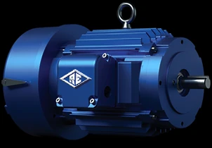
A Reuland brake motor is an AC induction motor with an integral, direct-acting magnetic disc brake on the shaft. The brake is spring-set and magnetically released — the spring holds the load whenever the coil is de-energized and the coil releases it to run — so the hold is fail-safe: the load is held the instant power is removed, an e-stop trips, or the line drops. Braking capacity spans 1.5 to 500 ft-lb on motors from 2 to 350 HP, making it the answer for cranes, hoists, bridges, saws, and spindles — any frequent start / stop / reverse duty where a load must not drift or coast. Choose a brake motor when the load has to be held without power; for the high-duty intermittent motor that drives the crane or hoist itself, the overhead crane & hoist motor is the companion.
Key Features & Benefits
- Holds the load the instant power is lost — the brake is spring-set, so it engages automatically whenever the coil is de-energized — on an e-stop, a tripped line, or a normal stop — rather than relying on power to hold. Fail-safe by design: the load does not drift or coast when the power goes away.
- One package instead of a motor plus a separate brake — the magnetic disc brake is built integral to the motor on a common shaft, so there is no coupling to align, no separate brake to mount, and a shorter, stiffer drive train. Less to install, less to keep in alignment, less to fail.
- Built for constant start, stop, and reverse — the heavy-duty lining and cast-iron brake housing are made for the frequent-cycling duty of cranes, hoists, saws, and spindles, where the brake works on every cycle. Sized for the work it actually does, not an occasional park brake.
- Brake torque matched to the load — braking capacity spans a wide range and is specified to the load being held or stopped, so the brake is neither undersized (drift) nor over-aggressive (shock to the driveline). The hold and the stop are engineered to the application, not a one-size catalog number.
- Runs across-the-line or on a drive — the same motor is available across-the-line or inverter/variable-speed, with feedback devices and thermal sensors added where the control scheme needs them. Drops into a contactor starter or a VFD-controlled positioning axis.
Specifications
- Operating principle
- AC induction motor with an integral direct-acting magnetic disc brake on the motor shaft. The brake is spring-set and magnetically released: the spring forces a friction disc against the braking surface to hold the shaft, and energizing the brake coil pulls the disc clear so the motor can run. Because the spring — not power — sets the brake, the hold is engaged whenever the coil is de-energized.
- Brake type & action
- Direct-acting magnetic disc brake with a heavy-duty, asbestos-free lining and a splined hub, in a cast-iron brake housing — seven major parts, only one of which moves (the armature). Spring-set (the brake holds with the coil de-energized) and magnetically released — a fail-safe / power-off hold that engages the instant power is removed, an e-stop is hit, or the line drops. An external manual release lever lets a held load be freed during a power outage. The lower-torque, economical MagnaStop brake (double-action ball-bearing cam, 1.5–20 ft-lb) is the alternative where its range fits.
- Braking torque
- Braking capacity from 1.5 to 500 ft-lb, matched to the load to be held or stopped (and to the deceleration the application requires). The disc brake mounting is interchangeable with Stearns, Dings, and other NEMA C-face brakes, so it retrofits where one of those is in service.
- Brake release
- Magnetically released by the brake coil; the brake disengages when the coil is energized and the spring re-sets the brake when it is de-energized. Specify the application’s hold and stopping duty with the order so the brake torque and coil are matched.
- Power range
- 2–350 HP.
- Speed / poles
- 3600, 1800, 1200, and 900 rpm (2-, 4-, 6-, and 8-pole); two-speed and variable-speed builds are available.
- NEMA design & motor type
- AC induction, NEMA Design B, C, or D, single- or two-speed; variable-speed (inverter) builds available. The design letter is selected for the load’s starting-torque and slip character.
- Frame size
- NEMA frames 56 through 449, in cast-iron or aluminum construction.
- Mounting
- Foot, footless, bracket, C- and D-flange, and metric DIN-flange mountings.
- Enclosure
- Motor: TEFC (totally enclosed fan-cooled), TENV (totally enclosed non-ventilated), or ODP (open drip-proof). The brake housing is IP2 rated as standard; IP54 dust-tight/waterproof and marine-duty (IEEE-45) brake enclosures, plus a brake space heater and moisture protection, are optional.
- Voltage / phase / frequency
- Motor up to 600 V, 3-phase, 60 Hz (to 133 Hz on an inverter), wound to order for other service voltages. The brake coil takes standard AC or DC voltages (a DC-rectified package is supplied with the brake on the larger frames).
- Insulation class
- Class B standard; Class F or H optional, with VPI (vacuum-pressure impregnation) for a void-free, moisture- and contamination-resistant winding.
- Bearings
- Steel ball, ceramic ball, or roller bearings, selected for the load and duty.
- Stator / rotor steel
- M-19, M-36, or M-45 electrical-steel laminations in the stator and rotor.
- Accessories
- Encoders, resolvers, temperature sensors, and vibration mounts are available where the application calls for position feedback, thermal protection, or isolation.
- Drive / control compatibility
- Across-the-line or inverter/variable-speed operation (to 133 Hz). The motor can be wound for the drive’s actual output voltage rather than full line voltage, which can reduce drive and feeder cost.
- Construction & manufacture
- Built in the USA — cast-iron or aluminum frame (in-house aluminum foundry), with machining, winding, assembly, and test in-house, and no minimum quantity (one motor or thousands), all engineered to order.
- Standards & recognition
- ISO 9001:2015 manufacture. Built to the application’s governing standards on request (crane/hoist duty, hazardous-area, and other qualifications are available on the engineered build).
- Build & lead time
- Custom build-to-order against drawing review — quote-only, lead time set per job. Expedited lead times are available based on factory capacity.
Common Applications
- Crane and hoist drives that must hold a suspended load on every stop
- Bridges and heavy movable structures requiring a fail-safe park brake
- Saws and cutting machines needing a fast, repeatable stop for safety and cycle time
- Spindles and positioning axes that must stop and hold precisely
- Conveyors and inclines where the load must not back-drive when power is removed
- Any frequent start / stop / reverse duty where coasting or drift is unacceptable
Design & Selection Considerations
- Size the brake torque to the load, not the motor — the brake must hold (and decelerate) the actual load with margin — an over-torqued brake slams the driveline on every stop, an under-torqued one lets the load creep. Use the input form to give us the load, the worst-case overhauling condition, and the stop you need. The brake is sized from the load it holds, not from the motor frame.
- A spring-set brake is a wear item — plan the lining — the friction lining wears with every cycle, and high-cycle hoist and saw duty wears it faster; the brake needs periodic inspection and eventual relining. Budget the inspection interval up front on a frequent-cycling machine.
- Manual release is a safety decision, not a default — a manual / hand release lets a held load be lowered with the motor de-energized — useful for maintenance, but it defeats the fail-safe hold while engaged, so whether to include it (and how it is interlocked) is a deliberate call. Decide the release strategy with the machine builder, not after the fact.
- Pick the enclosure for where the brake lives — brake dust and the environment both matter: a TEFC or TENV build keeps grit out of clean or outdoor service, while ODP suits a clean indoor location. Match the enclosure to the room, the wash-down, and the dust the brake itself sheds. The brake fouls faster in the wrong enclosure for the room.
- On a VFD, watch the winding and the bearings — a drive’s fast-switching waveform stresses the winding insulation and can drive shaft currents through the bearings; VPI insulation handles the voltage stress and bearing protection (or insulated bearings) addresses the currents. Use the input form to tell us the drive and how the motor will run. An inverter-duty build is specified to the drive, not assumed.
- Match the NEMA design to the load that starts it — a hard-starting or shock load wants a higher-torque (Design C) or high-slip (Design D) motor under the brake, not a general-purpose Design B; the brake holds, but the motor still has to start the load. The design letter follows the load’s starting and slip demand.
To spec the right Reuland brake motor:
Use the input form to send what the brake has to hold and stop — the load (and worst-case overhauling condition), the horsepower and speed, the NEMA design or starting-torque demand, the duty cycle (how often it starts, stops, and reverses), the available voltage and phase, the mounting and frame constraint, the enclosure environment, and whether it runs across-the-line or on a drive — and we’ll match the brake torque, the motor design, and the control package to your application.
Specialty Motors Application Sheet ›Talk to an engineer directly — Scott Prater, Principal · 917-580-0878 · scott@pratertechnical.com
Specifications compiled by Prater Technical Partners from Reuland Electric published product specifications.