Product Overview
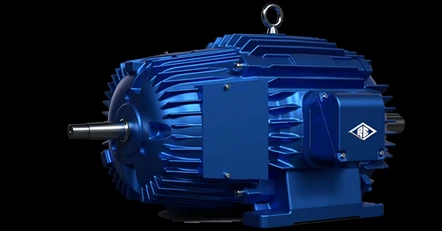
A wound-rotor (slip-ring) motor replaces the fixed squirrel cage with rotor windings brought out through slip rings to an external resistor bank — and by changing that resistance you adjust the motor’s starting current, starting torque, and running speed. That makes it the answer for heavy, high-inertia loads that need controlled high starting torque without a brutal inrush, and for stepped speed control on heavy intermittent duty — classic uses are large cranes and hoists, including refuse and scrap-handling cranes. Reuland Electric is one of the last U.S. manufacturers still building wound-rotor motors, with breakdown torque of 225% continuous and 275% intermittent. Choose wound-rotor where a VFD is unsuitable, or where a wound-rotor is being replaced in kind.
Key Features & Benefits
- Controlled high starting torque without a brutal inrush — putting resistance in the rotor circuit lets the motor develop strong starting torque while the line current stays in check — the reason wound-rotor motors start heavy, high-inertia loads that would trip a squirrel-cage motor across the line. Heavy starts, gentle on the supply.
- Stepped speed control on heavy intermittent duty — varying the external resistance changes the running speed under load, so a crane or hoist can be inched and feathered without a drive. Speed control where a VFD is unsuitable, or where a wound-rotor is being replaced in kind.
- Built for the crane-and-hoist duty cycle — the construction and duty ratings are matched to loads that start, reverse, and plug constantly — the pattern that defines bridge, trolley, and hoist service. A motor sized for how the load actually runs, not a continuous nameplate forced onto an intermittent job.
- Still made in the USA, and able to drop into an old installation — Reuland is one of the last U.S. manufacturers still building wound-rotor motors — foundry through final test in-house, with no minimum quantity, and able to match a discontinued OEM frame so a new motor fits the existing mounting. The right answer when the original is gone and a stock motor will not fit.
Specifications
- Operating principle
- AC induction motor with a wound rotor — instead of a fixed squirrel cage, the rotor carries three-phase windings whose ends are brought out through slip rings and brushes to an external circuit.
- Torque-speed character
- Starting torque, starting current, and running speed are all set by what is connected to the rotor circuit: adding external resistance raises starting torque while holding down inrush, and varying the resistance gives stepped speed control under heavy intermittent load — behavior a fixed squirrel-cage motor cannot deliver across the line.
- Rotor / slip-ring control
- Rotor windings terminate at slip rings and brushes wired to an external resistor bank (controller-supplied). Selecting resistance steps tailors the torque-speed curve to the load — the resistor controller is specified to the application.
- Breakdown torque
- 225% minimum for continuous duty; 275% minimum for intermittent duty.
- Power & speed
- Fractional through 250 HP; 4- through 12-pole windings (1800, 1200, 900, 720, and 600 rpm synchronous at 60 Hz). Running speed drops below synchronous as rotor resistance and load increase.
- Voltage / phase / frequency
- Through 600 VAC, 3-phase; 60, 50, 40, or 25 Hz.
- Frame sizes
- NEMA frames 56 through 449.
- Frame & end-bell construction
- Cast iron or cast aluminum frames and end bells.
- Stator / rotor laminations
- M-19, M-36, or M-45 electrical-steel laminations.
- Enclosure types
- Totally enclosed fan-cooled (TEFC) · totally enclosed auxiliary (force) cooled · totally enclosed non-ventilated (TENV) · open drip-proof (ODP).
- Insulation system
- Class F minimum, with Super B, F, or H systems available and VPI (vacuum-pressure impregnation) for a void-free, moisture- and contamination-resistant winding.
- Bearings & lubrication
- Steel ball or roller bearings.
- Mounting configurations
- Foot or footless; precision bracket; C, D, or metric DIN flange.
- Duty cycle ratings
- Continuous, and intermittent at 15-, 30-, 60-, and 120-minute ratings, plus special duty cycles built for heavy crane and hoist service.
- Accessories & options
- Built to order against drawing review — the rotor resistor controller, space heaters, and winding/bearing temperature sensors are specified per job. The full motor is engineered to the load, duty cycle, and environment.
- Approvals & documentation
- Built to order under Reuland’s in-house ISO 9001:2015 quality system, foundry through final test, with no minimum quantity. The wound-rotor rating is also available built to an obsolete OEM frame for in-kind replacement.
- Build & lead time
- Custom build-to-order — pricing is quote-only and lead time is set per job. Expedited lead times are available based on factory capacity.
Common Applications
- Hoists, and bridge and trolley drives on cranes, where starting torque and inching control matter
- Large refuse and scrap-handling cranes on 120-minute or continuous duty
- Plunger, centrifugal, and reciprocating-compressor loads with heavy, high-inertia starts
- Bending rolls and printing presses needing controlled acceleration
- Pulpers, pulverizers, stokers, and conveyors — high-inertia process loads
- In-kind replacement of an existing wound-rotor motor where the rotor-resistance controller is retained
Design & Selection Considerations
- The motor is only half the system — spec the resistor controller with it — a wound-rotor motor needs its external rotor-resistance controller to develop its torque-speed steps; the resistance plan is part of the design, not an afterthought. Use the input form to tell us the load and duty and the rotor circuit is sized with the motor.
- Slip rings and brushes are the maintenance item — the brushes wear and the rings need periodic inspection and cleaning — the trade-off for the control a wound rotor gives. Plan brush inspection into the maintenance schedule the way you would bearings.
- Match the duty rating to the real cycle — crane and hoist loads run intermittently; a 15-, 30-, 60-, or 120-minute rating is chosen to the actual on/off pattern so the motor sheds heat between cycles. Over-rate it and you pay for iron you do not use; under-rate it and the insulation cooks. Use the input form to give us the duty cycle, not just the horsepower.
- VFD or wound rotor? — decide before you spec — a VFD on a squirrel-cage motor now covers many adjustable-speed jobs, but a wound-rotor stays the answer where a drive is unsuitable or where an existing wound-rotor is being replaced in kind so the controller and wiring stay. If the installation is already wound-rotor, replacing in kind is usually the lower-risk path.
- Match the enclosure to the environment — TEFC is the industrial default for dust, moisture, and outdoor exposure; TENV where no external fan is wanted; ODP for clean indoor service. The enclosure is selected to where the motor lives, the insulation class to its thermal duty.
To spec the right Reuland wound-rotor motor:
Use the input form to send the load and what it drives, the horsepower and speed, the duty cycle (continuous or 15/30/60/120-minute), the supply voltage and phase, the enclosure environment, the mounting and frame constraints, and whether this is a new drive or an in-kind replacement — and we’ll spec the motor and its rotor-resistance controller to the application. For a replacement, send the old motor’s nameplate and photos from 5 feet away.
Specialty Motors Application Sheet ›Talk to an engineer directly — Scott Prater, Principal · 917-580-0878 · scott@pratertechnical.com
Specifications compiled by Prater Technical Partners from Reuland Electric published product specifications.