Product Overview
Reuland is a leading supplier of high-speed motors for automotive and aerospace test stands and dynamometers — variable-speed AC induction machines engineered to the test cell, reaching up to 50,000 rpm (60,000+ on consultation) and up to 1,500 HP at frequencies to 2,000 Hz. Hitting those numbers takes specialized construction: an encapsulated rotor, a hand-wound balanced stator, ABEC-7 precision or ceramic bearings, air / water / oil cooling, super Class H VPI insulation, and integrated sensors for the test-cell controller. Tilt-and-roll and tandem configurations extend the platform from a 60,000 rpm bearing rig to a high-torque driveline stand.
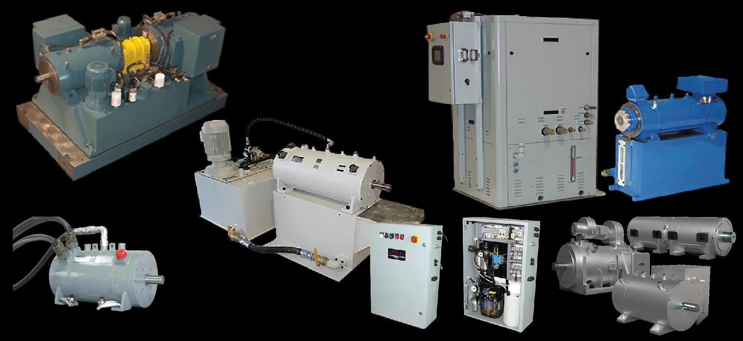
Key Features & Benefits
- Engineered to the test cell, not pulled from a catalog — the motor is designed around the unit under test and the drive that runs it — speed, power, frequency, and instrumentation are all specified to the rig. You get the machine the test plan needs, not the closest stock rating.
- Built to hold together at speed — an encapsulated rotor, hand-wound balanced stator, and precision bearings are what let the shaft run where an ordinary motor would fly apart or fail its bearings. The construction is the reason the speed is achievable.
- Cooling matched to a continuous-power duty — air, water, or oil cooling is selected so the motor sheds the heat of a sustained test run rather than tripping on temperature mid-test. The duty that breaks a fan-cooled motor is the design point here.
- Instrumented for closed-loop test control — integral encoders, resolvers, and temperature / vibration sensors hand the test-cell controller the feedback it needs to run and protect the rig. The motor is a measured node in the test system, not a black box.
- Tilts, rolls, and tandems for real driveline rigs — tilt-and-roll articulation and tandem pairing let the same platform serve chassis-dyno, driveline, and high-torque cells. One supplier from a 60,000 rpm bearing rig to a tandem high-torque stand.
Specifications
- Motor type
- AC induction, variable-speed motor engineered to the test cell — a custom high-speed / high-power machine driven by a variable-frequency drive, built to spin a test article (engine, transmission, EV traction motor, spindle, bearing rig) at a controlled speed and load rather than to drive a fixed production load.
- Speed range
- Up to 50,000 rpm standard, with higher speeds available on consultation with the factory. (Reuland frames the practical ceiling at 60,000+ rpm for ultra-high-speed builds.) The actual rating is set by the test article and drive.
- Power range
- Up to 1,500 HP (higher on consultation). Output is sized to the absorbed / driven power of the unit under test.
- Drive frequency
- Driven to up to 2,000 Hz — the high fundamental frequency is what makes the very high shaft speeds possible on a low pole count.
- Poles
- Typically 2- or 4-pole for a test stand — a low pole count is what lets the high drive frequency reach high shaft speed; Reuland winds 2 through 36 poles across the inverter-duty range, selected with the speed and frequency.
- Overload capacity
- 200% for 3 seconds, 150% for 60 seconds on typical designs — the short-term torque margin that lets the motor follow torque-pulse and transient test profiles rather than just hold a steady load. The exact margin is set per design.
- Rotor construction
- M-19 or M-36 electrical-steel laminations with a die-cast aluminum, copper, or copper-alloy cage. For ultra-high speed the rotor is an encapsulated design so it holds together at speed.
- Stator & winding
- M-19 or M-36 electrical-steel laminations, hand-wound for a balanced, symmetrical winding — balance is critical at test-stand speeds.
- Bearings
- High-precision ABEC-7 steel-ball, ceramic-ball, or roller bearings, selected for the speed and load. Oil-jet / oil-mist lubrication is used where the speed demands it.
- Cooling
- Air, water, or oil cooling to suit the duty — enclosure options include TEFC, A-TEFC, TENV, ODP, DPFC, A-DPFC, and water- / oil-cooled (TEWC, TELCW) constructions.
- Insulation system
- Super Class H insulation with vacuum-pressure impregnation (VPI) — the void-free winding handles the thermal and inverter-waveform stress of high-speed drive operation.
- Sensors & instrumentation
- Integrated encoders, resolvers, and temperature & vibration sensors (plus probe / gear speed pickups and a holding brake where required) report bearing and winding temperature, vibration, coolant temperature, and shaft position to the test-cell PLC or data logger.
- Tilt / roll & tandem
- Tilt-and-roll articulation in either direction for driveline and chassis-dyno rigs, and tandem pairing to double torque at a given speed.
- Voltage / phase
- Up to 600 V, 3-phase; the motor is wound to the drive’s output voltage rather than a fixed line voltage.
- Drive / control
- Variable-frequency (inverter / vector) drive by nature — the motor is engineered for, and wound to, the specific drive that controls speed and torque in the test cell.
- Enclosure
- TEFC / A-TEFC / TENV / ODP / DPFC / A-DPFC and water- / oil-cooled (TEWC / TELCW) enclosures — matched to the cell environment and the cooling medium.
- Approvals & qualification
- Built to order for automotive, aerospace, and military test programs; qualification (documentation, witnessed test) is matched to the program and specified per job.
- Build & lead time
- Custom-engineered to the test cell, built foundry-through-final-test in the USA with no minimum quantity. Pricing is quote-only and lead time is set per job; expedited lead times are available based on factory capacity.
Common Applications
- EV and hybrid traction-motor and transmission test stands
- Engine and powertrain dynamometers — final test, durability, NVH, and cold-cell
- Engine torque-pulse and inertia simulation for combustion-engine development
- Gear, drive-train, and component test stands — including aerospace test cells to 60,000 rpm
- Accessory test — fuel-pump, power-steering pump, clutch, and water-pump / alternator / air-compressor
- Chassis-dyno and driveline rigs using tilt-and-roll articulation
Design & Selection Considerations
- Specify the speed-vs-power envelope, not a single peak number — a test motor lives on a torque-speed curve; the constant-torque and constant-power regions, and the peak vs. continuous points, all drive the design. Use the input form to give us the full duty profile the article imposes. A lone “max rpm” or “max HP” under-specifies a test stand.
- Pick the bearing and lubrication to the speed first — ABEC-7 steel, ceramic hybrid, and roller bearings each have a speed / load / life trade-off, and high speed wants oil-jet or oil-mist rather than grease. The bearing decision is made before the frame. Bearings are the usual life limit on a high-speed motor.
- Match the cooling medium to the test environment — water or oil cooling removes far more heat than air and shrinks the frame, but adds plumbing and a coolant loop to the cell; air cooling is simpler but limits continuous power. Decide what the cell can plumb. The cooling choice ripples into the whole rig layout.
- Treat the drive as part of the motor spec — because it is inverter-driven by nature, the winding is matched to the drive’s output and the insulation (super Class H, VPI) is rated for the switching waveform; bearing protection addresses shaft currents. Use the input form to tell us the drive model. The drive is a design input, not an afterthought.
- Plan the sensor and brake suite up front — encoders, resolvers, temperature and vibration sensors, and any holding brake are integrated into the build, not bolted on later — define what the controller needs to read and trip on. Retrofitting feedback onto a finished high-speed rotor is far harder than designing it in.
To spec the right Reuland test-stand motor:
Use the input form to send the unit under test and its speed / power / torque profile, the drive model, the cooling the cell can plumb, and the feedback the controller needs — with the cell environment and any program qualification — and we’ll work the test-stand motor up with Reuland against your rig.
Specialty Motors Application Sheet ›Talk to an engineer directly — Scott Prater, Principal · 917-580-0878 · scott@pratertechnical.com
Specifications compiled by Prater Technical Partners from Reuland Electric published product specifications.