Product Overview
The ATi A14 / A11 is the modular GasSens monitoring system — a component approach where you assemble the controller from DIN-rail modules instead of buying a fixed-channel box. Each gas point gets its own receiver module (4-digit LED, isolated 4–20 mA, three assignable alarm relays, trouble alarm), fed by a digital two-wire sensor/transmitter up to 1,000 ft away on unshielded, non-polarity-sensitive cable. A universal power-supply module (85–265 V AC or DC) feeds one or two receivers and charges an optional battery backup; horn and strobe modules round out the alarm. Standard NEMA 4X enclosures hold up to six modules, with custom enclosures for larger systems. It is the right tier when each point needs its own relays and analog output for local control — below a plant-wide addressable network, above a single receiver.
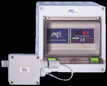
Key Features & Benefits
- A system you assemble, not a box you outgrow — receiver, power-supply, battery-backup and horn/strobe modules clip to DIN rail in NEMA 4X enclosures sized for 1 to 6 points, with custom enclosures above that — add a point by adding a receiver, not by replacing the panel. Start at the size you need and grow it.
- Per-channel relays and analog, not a shared bus — every receiver carries its own isolated 4–20 mA and three assignable alarm relays, so each point can drive its own local control — valve shutoff, horn, telemetry — independently of the others. Point-level control without a PLC in the loop.
- Long, forgiving sensor wiring — the two-wire current-pulse link runs unshielded cable up to 1,000 ft and is not polarity-sensitive, so a reversed pair will not damage anything or read wrong. Field wiring is hard to get wrong.
- Optional Auto-Test on the transmitters — most sensor/transmitters accept the Auto-Test gas generator: every 24 h the receiver fires a real gas sample at the sensor and confirms it responds, flagging a blocked membrane or end-of-life cell on the trouble relay. Scheduled real-gas proof, hands-off.
Specifications
- Function
- Modular multi-point gas-detection and alarm system — per-channel receiver modules read the sensor/transmitters, drive alarm relays and analog retransmission, and a universal power-supply module feeds them; build a system from one channel to as many points as the enclosure holds.
- Sensor / transmitter inputs
- Digital two-wire sensor/transmitter — a current-pulse-position signal over unshielded cable, not polarity-sensitive (incorrect wiring is virtually eliminated). Transmitters are shielded NEMA 4X (designed to meet intrinsic-safety standards) or an explosion-proof version; combustible-gas transmitters are always explosion-proof. One receiver module per sensor/transmitter.
- Channels / capacity
- One receiver per point; standard NEMA 4X enclosures house up to 6 modules (single, two-, three- and six-module sizes), with custom enclosures for larger systems — or mount the 35 mm DIN-rail modules in your own panel.
- Sensor-to-receiver distance
- Sensor/transmitters locate up to 1,000 ft (300 m) from the receiver module on two-wire unshielded cable.
- Display
- 4-digit LED per receiver, reading directly in ppm, ppb or %; a sunlight-readable high-intensity mode for outdoor use, normal mode indoors. A front-panel LED bar with gas-symbol overlay identifies the gas.
- Alarm levels / setpoints
- Two adjustable concentration setpoints per receiver (WARNING low, ALARM high), each settable from 5–100% of range; WARNING non-latching, ALARM latching, and each switch-selectable to trip above or below the setpoint. A selectable 2 s or 10 s alarm delay rides through transients. A separate trouble alarm activates on loss of sensor/transmitter input or on a failed Auto-Test (where fitted).
- Relay / analog outputs
- Per receiver: isolated 4–20 mA (1,000 Ω max load) plus three assignable SPDT alarm relays (10 A @ 120 VAC / 5 A @ 250 VAC resistive), each configurable normal/fail-safe, latching/non-latching and fast/slow, and assignable to either setpoint; a fourth SPDT trouble relay is factory-set fail-safe. Front-panel and remote reset acknowledge and silence; a single horn can be wired through several receivers.
- Power
- Receiver: 9–15 VDC, 300 mA max from the power-supply module. The universal power-supply module accepts 85–265 V AC or DC (50/60 Hz, self-regulating, no jumpers) and outputs regulated 13.7 VDC for one or two receivers plus battery-backup charging, with a power-fail relay. An optional 12 V 4 Ah battery backup holds a single point ~12–24 h.
- Enclosure / rating
- Modules: Noryl, 2.8 × 3.6 × 2.3 in (70 × 90 × 58 mm), −40 to +55°C, 0–99% RH non-condensing. System enclosures: NEMA 4X polystyrene in single-, two-, three- and six-module sizes (custom above that); battery backup in NEMA 4X. For a classified area the receiver and power-supply modules are also offered in explosion-proof enclosures, Class I, Div 1, Groups C & D (Group B available). Sensor/transmitter: NEMA 4X or explosion-proof.
- Mounting
- Modules clip to 35 × 7.5 mm DIN rail; all field connections land on quick-disconnect plug-in terminal blocks, so a module swaps out in minutes.
Common Applications
- Chemical and petrochemical plants — multi-point toxic and combustible coverage with per-point shutoff relays
- Semiconductor fabrication — distributed hydride and toxic monitoring across a tool bay
- Water and wastewater treatment — chlorine, chlorine dioxide and ozone points around feed and storage
- Food processing and refrigeration — ammonia area monitoring with local horn and shutoff
- Pulp & paper and mineral processing — mixed toxic / combustible safety points on one panel
What to Pair It With
The A14/A11 is the controller half of the system — it reads ATi digital two-wire sensor/transmitters, one receiver per point. Match the transmitter to the gas and the area:
- B12 two-wire transmitter — the loop-powered B12 toxic transmitter is the workhorse sensor point — electrochemical cells for ~30 toxic gases, NEMA 4X or explosion-proof, with the B12 Wet variant for permanently saturated streams.
- C12-17 combustible transmitter — for combustible %LEL points the C12-17 catalytic-bead transmitter is always the explosion-proof build — one receiver channel reads it the same way it reads a toxic point.
- D12 / F12 for classified or full-feature points — where a point needs the explosion-proof full-feature transmitter or its own local display, the D12 and F12 family feed the same modular system; tell us the area classification per point.
- Auto-Test, horn, strobe and battery-backup modules — most sensor/transmitters accept the Auto-Test real-gas generator; the system adds 12 VDC horn, xenon strobe and battery-backup modules so the alarm and ride-through are built into the same enclosure.
Design & Selection Considerations
- Size the system by point count and per-point control needs — each point takes one receiver module, and standard NEMA 4X enclosures hold up to six modules (custom enclosures above that) — budget a power-supply slot for every one or two receivers. The A14/A11 earns its place where every point must drive its own local control independently — its own relays and analog feed; for a single point a B14 receiver is simpler, and for a large addressable network a GasSens Midi is cheaper per point. Use the input form to tell us the point count and what each point must switch, and the module and enclosure mix is specified to match.
- Plan the sensor runs around the 1,000-ft limit — sensor/transmitters sit up to 1,000 ft from the receiver on two-wire unshielded cable; place receivers in a central panel and run cable out to where each gas collects, rather than dropping a receiver at every sensor. The link is not polarity-sensitive, which removes a common installation error — but the 1,000 ft ceiling sets how far the panel can be from the most distant point. Map the worst-case run first.
- Decide the relay strategy and fail-safe convention per point — each receiver gives two concentration setpoints (WARNING / ALARM, 5–100% of range) and three assignable relays configurable normal or fail-safe, latching or non-latching, fast or slow — settle, per point, which level trips which relay, whether a tripped relay latches until reset, and whether the contacts are energized-normal (fail-safe) so a wiring fault alarms. The trouble relay is factory fail-safe. Fail-safe plus latching is the usual life-safety convention; confirm it against your alarm matrix.
- Specify backup power where a power loss cannot blind the system — the universal power supply runs on 85–265 V AC or DC and has a power-fail relay; the optional 12 V 4 Ah battery backup holds a single point ~12–24 h (less in sunlight-display or fail-safe-relay modes). For continuous-coverage areas, add the battery module and route the power-fail relay to your annunciator. Use the input form to tell us the required ride-through and the backup is sized to it.
To spec the right A14 / A11 gas system:
Use the input form to tell us the target gas and its range, the background atmosphere, the area classification, and how many points you need to watch — and we’ll spec the sensor chemistry, transmitter, holder and controller for your application.
Gas Detection Application Sheet ›Talk to an engineer directly — Scott Prater, Principal · 917-580-0878 · scott@pratertechnical.com
Specifications compiled by Prater Technical Partners from Badger Meter ATi / GasSens gas-detection product literature.