Product Overview
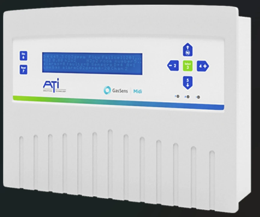
The ATi GasSens Midi is the networked controller in the GasSens line — built for plant-wide and building-wide systems where a single cable beats dozens of individual transmitter loops. One control unit polls up to 64 addressable sensors over a single four-core CANbus cable (to 1 km, extendable with boosters), and the same architecture scales to 1,024 sensors across sixteen Midi units. The 4-line dot-matrix LCD names the reporting sensor, gas, concentration and alarm or fault status; three alarm levels with time-to-alarm and 8 zone/voting outputs drive a relay bank (2 DPCO + 6 SPCO, 5 A @ 230 VAC), and Modbus RS-485 with a built-in event log hands the whole network to a BMS or SCADA. It is the right tier when many points, central display and integration matter more than per-point dedicated control; below it, the A14/A11 and B14 handle mid-size and single-point systems.
Key Features & Benefits
- 64 sensors on one four-core cable — a single CANbus run links up to 64 addressable sensors to one control unit, so a plant-wide system is one home-run cable with sensors tapped in where the gas collects — not 64 individual transmitter loops. One cable does the work of a wiring harness.
- Scales to 1,024 points across 16 units — multiple Midi units rack-mount or sit under a network controller for up to 1,024 addressable sensors, so the same architecture covers a single room or an entire site. One platform from 1 point to 1,024.
- Three alarm levels, zone voting and a full event log — three alarm levels with time-to-alarm, 8 zone/voting outputs, and a built-in event log plus per-sensor logging (2,880 readings) give an auditable record and area-based alarm logic, not just point trips. Area logic and history, on board.
- Modbus and self-diagnostics for integration — Modbus RS-485 (and RS-232 data log) hands the whole network to a BMS or SCADA, and continuous automatic safety-check diagnostics flag sensor-line, sensor and system faults distinctly. One Modbus tag set for the building.
Specifications
- Function
- Networked multi-point gas-monitoring controller — one control unit continuously polls a network of addressable sensors over a single four-core cable, displays the reporting sensor, gas type, concentration and alarm status, and activates analog, digital and user-selectable relay outputs by alarm level.
- Sensor / transmitter inputs
- Pre-calibrated addressable digital gas sensors on a CANbus network; sensors are added at any point on the cable and report their location, gas type and concentration to the control unit.
- Channels / capacity
- 1–64 addressable sensors per Midi unit, capable of measuring 60+ different gases or vapors.
- Sensor-to-receiver distance
- Single four-core network cable (1.5 mm² screened, 2 power + 2 comms) to a maximum 1 km; an optional signal booster extends a further 1 km per booster.
- Display
- Dot-matrix LCD, 4-line × 40-character — indicates sensor location, gas type (rising or falling alarms), alarm status, system fault, sensor-line fault, sensor fault, inhibit, real-time clock and event memory; global red ALARM, amber FAULT and amber INHIBIT LEDs.
- Alarm levels / setpoints
- Three alarm levels with a time-to-alarm option, plus 8 user-selectable zone/voting outputs (NE/ND with de-energize delay). Automatic safety-check diagnostics run continuously.
- Relay / analog outputs
- Relays: 2 DPCO + 6 SPCO rated 5 A @ 230 VAC, factory-set as common low (DPCO), high (DPCO), over-range (SPCO) and fault (SPCO) alarms with four user-selectable SPCO groups; a resettable general-alarm SPCO drives sounders, and an inhibit remote-indicator relay. Analog and digital data outputs follow alarm level.
- Communication
- Modbus RS-485 and RS-232 data-log output; parameter setup via PC or front panel. An event log and per-sensor logging (1–60 min intervals, 2,880 readings stored) are built in.
- Networking
- Up to 1,024 addressable sensors — multiple Midi units in a 19-inch rack, or a network controller supervising up to 16 Midi units.
- Power
- 230/115 V AC or 24 V DC ±15%. Control unit 7.5 W quiescent, 17 W full alarm; each sensor 1.25 W. The internal supply powers up to 35 sensors; 36+ sensors need the 11 A / 24 VDC auxiliary power pack.
- Enclosure / rating
- Control unit IP52, wall-mount (optional over-housing IP65); cable entry bottom, rear or top. Operating temperature −10 to 50 °C. 315 × 265 × 95 mm.
- Mounting
- Wall-mount control unit; multi-unit systems mount in a 19-inch rack. Remote reset / mute terminals provided.
Common Applications
- Car parks, tunnels and enclosed bays — CO and NO₂ monitoring tied to ventilation control
- Water and wastewater treatment works — chlorine, chlorine dioxide and ozone points across the plant
- Boiler and plant rooms, breweries and process plants — combustible and toxic area coverage on one network
- Public and commercial buildings, hotels and offices — life-safety gas monitoring integrated with building air-handling
- Horticulture and manufacturing — multi-zone CO₂ and toxic monitoring with central display and Modbus
What to Pair It With
The Midi is the network controller — it polls addressable GasSens sensors on the CANbus and hands the system to a BMS over Modbus. Match the sensing and the fixed-point hardware:
- Addressable GasSens sensors on the CANbus — the Midi ships with pre-calibrated addressable sensors that tap onto the four-core network; the sensor chemistry follows the gas, the same way it does for the fixed B12 and C12-17 transmitters — tell us each gas and range and the sensors are specified per point.
- Fixed 4–20 mA transmitters where a point sits off the network — a point too far from the CANbus or in a classified area can run a standalone D12 or F12 transmitter and report into the system separately; tell us which points are on-network versus standalone.
- Auxiliary power pack for larger sensor counts — the internal supply powers up to 35 sensors; beyond that the 11 A / 24 VDC auxiliary power pack is required — sized to the final sensor count.
- Signal boosters and the network controller for big systems — a signal booster extends the CANbus a further 1 km per unit, and a network controller (or a 19-inch rack of Midi units) supervises up to 16 units / 1,024 sensors for a full-site system.
Design & Selection Considerations
- Choose the Midi when point count and cabling win — the Midi earns its place when you have many points and a single CANbus home-run beats pulling an individual 4–20 mA loop to each one — up to 64 sensors per unit, 1,024 across sixteen. For one point a B14 receiver is far simpler, and where each point needs its own dedicated control relays the modular A14/A11 fits better. Many points, one cable, central display and Modbus → Midi.
- Lay out the CANbus run within the 1 km limit — the four-core network cable reaches 1 km on its own and a further 1 km per signal booster, so the farthest sensor and the booster count fall out of the cable topology, not the sensor total — walk the route before you fix sensor addresses. The total sensor count then drives the power side: past 35 sensors the auxiliary power pack comes in (see What to pair it with). Map the run length first, then the point count — one sets the cable and boosters, the other sets the power.
- Define alarm levels, zones and voting before commissioning — three alarm levels with time-to-alarm and 8 user-selectable zone/voting outputs let you alarm by area and require multiple sensors to agree before a major action — decide the per-zone setpoints, which level drives which relay group (2 DPCO + 6 SPCO, 5 A @ 230 VAC), and whether contacts de-energize on alarm (NE/ND). Bring the zone-and-voting matrix and the relay map is configured to it.
- Plan the Modbus / BMS integration and logging — Modbus RS-485 carries every sensor reading and status to a BMS or SCADA, and the built-in event log plus per-sensor logging (1–60 min intervals, 2,880 readings) hold the on-board history — settle the register map, polling rate and which faults (sensor-line, sensor, system) the host must annunciate separately. Use the input form to tell us the host system and the integration is scoped up front.
To spec the right GasSens Midi controller:
Use the input form to tell us the target gas and its range, the background atmosphere, the area classification, and how many points you need to watch — and we’ll spec the sensor chemistry, transmitter, holder and controller for your application.
Gas Detection Application Sheet ›Talk to an engineer directly — Scott Prater, Principal · 917-580-0878 · scott@pratertechnical.com
Specifications compiled by Prater Technical Partners from Badger Meter ATi / GasSens gas-detection product literature.