Product Overview
The FC-5000 is the full-featured Cox flow computer, built on one platform in two configurations. The Flow Computer totalizes the pulse from one or two Cox turbine meters and, with a temperature input, applies Roshko / Strouhal compensation — correcting for fluid viscosity and for thermal expansion of the meter housing — so the reading stays true as the fluid warms or cools. The BTU Monitor trades a flow channel for a second temperature input and computes hydronic energy and BTU to EN 1434. Both add 100-point linearization, user-programmable relays for totalizing output and alarms, scaled analog and frequency outputs, six isolated digital channels for remote reset, and standard EIA-485 with selectable Modbus or BACnet; the scaled-output set, relay form and mounting are specified at order time. It runs on a 128 × 64-pixel graphical LCD, takes wide-range DC or AC power, and mounts in a panel or a NEMA 4X / IP67 field enclosure.
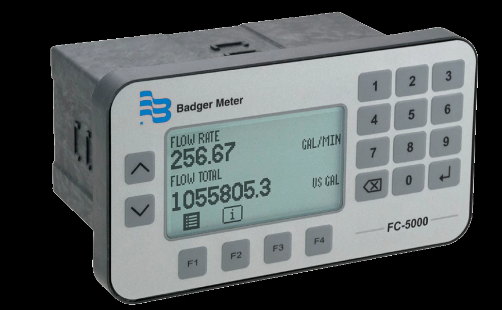
One platform, two configurations
The FC-5000 is ordered in one of two configurations off the same hardware — tell us whether the job needs energy / BTU and we’ll specify the right one.
- One or two flow channels, with an optional temperature input
- 100-point linearization, Roshko / Strouhal temperature compensation (with the temperature input)
- Volumetric and mass totalizing (no energy / BTU)
- One flow channel with two temperature inputs
- Energy rate and total — BTU, kBTU, kW or tons of refrigeration, to EN 1434
- RTD or thermistor on supply and return
Key Features & Benefits
- Temperature-compensated reading — reads an RTD or thermistor and applies Roshko / Strouhal compensation for fluid viscosity and meter thermal expansion, so a Cox turbine reading holds through changing fluid temperature
- 100-point linearization — a fine K-factor curve straightens the meter output across its flow band
- Energy / BTU computation — in the BTU Monitor configuration a temperature pair turns flow and ΔT into hydronic energy — BTU, kBTU, kW or tons of refrigeration, to EN 1434
- Programmable relays — user-programmable Form C and Form A relays drive a totalizing output or fire an alarm on rate, total or temperature
- Configurable scaled outputs — two scaled analog (0–5 V, 0–10 V or 4–20 mA) or frequency (1–4000 Hz) channels plus six isolated digital channels for remote reset — the output set is specified at order time
- Open protocols — a standard EIA-485 port carries Modbus RTU / ASCII or BACnet, selectable in firmware, with up to 255 units on one daisy-chain
- Single or dual channel — one or two flow channels, on a 128 × 64-pixel LED-backlit graphical LCD
- Panel or wall mount — a panel cutout for a control room or a NEMA 4X / IP67 enclosure for the field
Specifications
- Function
- Microprocessor flow / energy computer — totalizes the pulse from a Cox turbine meter, applies temperature compensation, and (in the BTU Monitor configuration) computes hydronic energy / BTU
- Meter compatibility
- Cox turbine meters, with an RTD or thermistor temperature input
- Channels
- Flow Computer: one or two flow channels, with an optional temperature input. BTU Monitor: one flow channel with two temperature inputs
- Flow-meter input
- 0.3 Hz–10 kHz; configurable as a 0–30 V square-wave pulse (2.5 V threshold) or a zero-centered sine wave (45 mV threshold)
- Temperature inputs
- Platinum 100 / 1000 Ω RTD (2-, 3- or 4-wire, Callendar–Van Dusen) or Type II thermistor (Steinhart–Hart)
- Viscosity / temperature compensation
- Roshko / Strouhal temperature compensation — with a temperature input it corrects for changing fluid viscosity and for thermal expansion of the meter housing, so the reading holds as the fluid warms or cools
- Analog output
- Two scaled channels (option A) — 0–5 V, 0–10 V or 4–20 mA, ±0.1% of reading, 16-bit (15-bit on 0–5 V)
- Frequency output
- Two scaled TTL channels (option F) — 1–4000 Hz, ±0.01% of reading
- Relay outputs
- Two Form C mechanical relays, or one Form C mechanical plus one Form A solid-state (selected at order time); each is user-programmable as a totalizing output or as an alarm on rate, total or temperature
- Digital I/O
- Six isolated channels for remote reset of relays, totalizers, or both
- Communication options
- EIA-485 (RS-485); Modbus RTU, Modbus ASCII or BACnet, selectable in firmware; up to 255 units on one daisy-chain
- Display
- 128 × 64-pixel LED-backlit graphical LCD, single- or dual-view
- Power supply
- 10–40 V DC or 9–28 V AC RMS (50–60 Hz)
- Mounting
- Panel mount, or wall mount in a NEMA 4X / IP67 enclosure — selected at order time
- Flow units
- Gallons, liters, cubic meters, cubic feet, barrels, acre-feet, ounces or custom
- Energy units
- BTU, kBTU, kW or tons of refrigeration (RT) — BTU Monitor configuration, to EN 1434
Common Applications
- Temperature-compensated flow on fluids whose viscosity drifts with temperature
- Hydronic energy / BTU measurement on chilled- and hot-water loops (BTU Monitor)
- Rate, total or temperature alarms and a totalizing relay output to a control panel
- Feeding a PLC, DCS or building automation system over Modbus or BACnet
- Dual-flow-channel totalizing, or single-flow with a supply / return temperature pair
To size & select the right FC-5000:
Use the input form to send your Cox meter, the fluid and its temperature range, and the outputs and protocol you need — and whether you need energy / BTU — and we’ll configure the FC-5000 channels, I/O and communications for your application.
Flow Meter Application Sheet ›Talk to an engineer directly — Scott Prater, Principal · 917-580-0878 · scott@pratertechnical.com
Specifications compiled by Prater Technical Partners from Badger Meter Cox precision turbine product literature.