Product Overview
The aluminum Industrial Oval Gear meter trades the corrosion margin of stainless for a lighter, lower-cost body aimed squarely at petroleum duty — hydraulic and lube oils, diesel and fuel oils that do not attack aluminum. The metering principle is identical to the rest of the line: paired oval rotors sweep a fixed volume per revolution, so it reads actual volume — ±0.5% of reading above 5 cP, ±0.03% repeatable and unaffected by viscosity shifts — in a 6061 aluminum housing rated to 2,000 psi through the 1 in. body. It spans 1/4 to 3 in. in NPT, BSP, ANSI 150# and DIN flange, reads in any orientation with no straight run, and tops with the local ILR display, the ER-420 counter, the ER-500 monitor or an F-series register. Standard rotors handle 1,000 mPas and the high-viscosity option reaches 500,000 mPas for heavy oils. When the fluid would attack aluminum, the identical meter is available in 316L stainless or PVDF.
Key Features & Benefits
- Lighter and lower-cost — the aluminum body cuts weight and price for petroleum and fuel duty where the corrosion resistance of stainless is not needed
- Built for fuel and lube dispensing — the standard choice for diesel, fuel-oil and lubricant batching and dispensing on mobile equipment, fuel skids and lube rooms
- Reading holds as the fluid thickens or thins — a meter calibrated on one oil stays accurate as temperature moves the viscosity — oil that thickens cold does not pull the reading off
- No flow conditioning to engineer — it reads without upstream straight pipe, so it drops into tight fuel and lube plumbing on equipment and packaged skids
- Field-recalibratable — the electronic register holds the calibration factor in non-volatile memory and can be recalibrated in the field as fluids or duty change
- Step up to stainless when the fluid demands it — the same meter is available in a 316L body for higher pressure or aggressive fluids, so the platform scales with the application
Specifications
- Measurement principle
- Positive displacement — paired oval rotors mesh in the metering chamber and sweep a fixed volume of fluid per revolution; magnets on the rotor ends trip a sensor in the register, so the rotation count is a true volume measurement, not an inference from velocity
- Service / fluids
- The lighter, lower-cost body for petroleum-based service — hydraulic and lube oils, fuels, diesel and other fluids compatible with aluminum; the value choice for fuel and lubricant dispensing and batching
- Accuracy
- ±0.5% of reading on fluids above 5 cP in the 1/2 in. and larger sizes; ±1.0% (>5 cP) / ±1.5% (<5 cP) on the 1/4 in. meters
- Repeatability
- ±0.03%
- Flow range
- 0.067 to 185 US GPM (0.25 to 700 l/min) across the aluminum size range, including a 1 in. high-flow body
- Sizes
- 1/4, 1/2, 3/4, 1, 1 high-flow, 1-1/2, 2 and 3 in.
- Viscosity
- To 1,000 mPas with standard rotors; to 500,000 mPas with the high-viscosity (HV) modified rotors
- Body material
- 6061 / 6082 aluminum (housing and cover)
- Rotor materials
- 316L stainless, Ryton (PPS) or Vectra (LCP), selected to the fluid
- Spindle / bearings
- 316L stainless spindle; graphite bearings
- O-rings / seals
- Viton, Aflas, Kalrez or EPDM o-rings, matched to the fluid
- Process / fluid temperature
- −22 to 240°F (−30 to 120°C); PPS / LCP plastic rotors are rated to 176°F (80°C)
- Pressure rating
- 2,000 psi (140 bar) NPT / BSP in the 1/2 to 1 in. sizes; 940 psi at 1/4 in.; 720 / 580 / 360 psi (NPT / BSP) at 1-1/2 / 2 / 3 in. ANSI 150# flange 275 psi; DIN flange 230 psi (flanges offered from 1 in. HF up). Higher ratings on request
- Process connections
- NPT, BSP, ANSI 150# flange and DIN flange (EN 1092-1)
- Registers / outputs
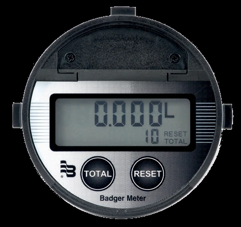
- Meter-mounted ILR-700 / 701 / 750 local display (9-point linearization on the 701 and 750; scalable pulse and 4–20 mA on the 750), the ER-420 4–20 mA counter, the ER-500 flow monitor (Modbus RTU), or the advanced F-series; NAMUR / PNP / NPN / reed / Hall sensor boards for raw pulse. The ILR series does not fit the 3 in. meter — size the register with the body
- Hazardous-area sensors
- Intrinsically safe NPN / PNP open-collector and NAMUR sensors — Class I, II and III, Division 1 (Groups A–G) in the USA and Canada, with ATEX and IECEx Ex ia IIC approvals
- Options
- High-viscosity (HV) rotors; 5-point calibration report; linearization with a 5-point calibration report (ILR-750 / ILR-701 only); 3.1 material certificate; silicone-free build; meter serialization
- Certifications / documentation
- Certificate of Conformance; NIST-traceable calibration certificate; EN 10204 3.1 material certificate for the pressurized aluminum housing
- Calibration
- Factory-calibrated and field-recalibratable through the electronic register; 5-point calibration report available as a documented option to be specified at time of order
Common Applications
- Diesel, fuel-oil and gasoline dispensing and batching on fuel skids and mobile equipment
- Lubricant and hydraulic-oil metering to bearings, gearboxes and lube rooms
- Engine and generator fuel-consumption measurement
- Oil and additive batching on packaged blending equipment
- Burner and boiler fuel-oil totalizing
Design & Selection Considerations
- Chemistry and pressure set the body — the body alloy is the first decision and it is fluid-driven: 316L stainless is the industrial workhorse, the highest-pressure body with the widest fluid compatibility; 6061 aluminum is the lighter, lower-cost body for petroleum, lubricants and fuel where the fluid is aluminum-compatible; and Kynar (PVDF) is the all-plastic body (Hastelloy-C spindle) for acids, caustics and solvents that attack metal. Pressure capability follows the body alloy, and it also falls as the size grows and as you move from threaded to flanged ports, so the alloy and the connection are decided together. Use the input form to give us the fluid and the working pressure together and we’ll set the body and the connection.
- Viscosity sets the rotor; chemistry sets the wetted stack — standard rotors handle fluids to 1,000 mPas; for greases, heavy oils, polymers and adhesives the high-viscosity (HV) modified rotors run to 500,000 mPas — an order option on the same body, not a separate model. Within the meter the rotor and o-ring materials are matched to the fluid, so the whole wetted path is spec’d to service. Use the input form to tell us the fluid and its viscosity at operating temperature and we’ll specify standard or HV rotors with the right seals.
- It is a positive-displacement meter — no straight run, any orientation — because the measurement is mechanical displacement rather than velocity, the meter needs no upstream straight pipe run or flow conditioning, reads true in any orientation and in tight pipework, and is unaffected by viscosity shifts and pulsating flow. That is the opposite of a turbine or paddlewheel, whose reading moves with the flow profile. It is the meter for accurate batching and totalizing where a velocity meter would need pipe it does not have.
- Keep the fluid reasonably clean — the oval rotors mesh on close tolerances, so abrasive grit and hard particulate are the wear enemy — a strainer ahead of the meter protects the gears on debris-prone fluids, and the meter is not the right choice for abrasive slurries. Use the input form to tell us the fluid’s cleanliness and we’ll advise on upstream filtration.
- Size to the flow, not the pipe — each port size covers its own flow band, with a dedicated low-flow body at the bottom of the range and a high-flow body at the top, and the meter reads its tightest accuracy class in the larger sizes on fluids above 5 cP — so the right size is the one that runs mid-band at your normal flow, not the one that matches the line. Use the input form to send the normal and maximum flow and we’ll pick the size that reads mid-band at your pressure.
- Pick the register for what the reading has to do — the meter mounts a register or sensor on top, and the choice follows the host: a local display at the meter (ILR family), a remote analog counter (ER-420), a monitor with alarms and a fieldbus (ER-500), or the advanced F-series for HART, RS-485 or batch control — with intrinsically safe sensors where the area is classified. Use the input form to tell us the output, protocol, power and area classification and we’ll configure the register into the part number.
To size & select the right Aluminum oval-gear meter:
Use the input form to send your fluid, its viscosity at operating temperature, the normal and maximum flow, the line size and the working pressure — with any corrosion or hazardous-area requirement — and we’ll spec the body alloy, rotors, seals, connection and the ILR, ER or F-series register for your application.
Flow Meter Application Sheet ›Talk to an engineer directly — Scott Prater, Principal · 917-580-0878 · scott@pratertechnical.com
Specifications compiled by Prater Technical Partners from Badger Meter Industrial Oval Gear positive-displacement meter product literature.