Product Overview
The Blancett QuikSert Explosion-Proof is the compact between-the-flange wafer turbine built for hazardous locations — rated Class I, Division 1, Groups C and D for liquid metering in oil & gas, chemical and other classified areas. A helical rotor turns in proportion to flow and is read by a hazardous-area magnetic pickup (ordered separately), putting out an AC pulse whose frequency tracks volumetric flow, held to ±1% of reading at ±0.1% repeatability over a 10:1 range with a NIST-traceable water calibration and unique K-factor on every meter. Built in 316 stainless with a CD4MCu rotor and tungsten-carbide internals, it spans 1–10 in. and 0.6–5,000 gpm, mounts between ASME flanges with centering rings and studs, and runs −150…350°F. For a local readout in the classified area it pairs with the explosion-proof B3150 monitor; IFC converters and K-factor scalers carry a scaled-pulse or 4–20 mA signal out to a monitor or control system in a safe area.
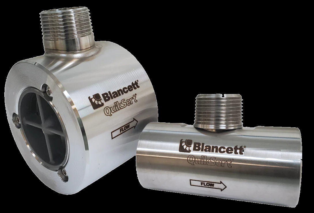
Key Features & Benefits
- Built for Class I, Div 1 — an explosion-proof wafer turbine rated for Groups C and D hazardous locations, with a hazardous-area magnetic pickup ordered to suit
- Compact between-flange body — a short face-to-face that drops in between standard flanges — ideal for tight skids and short pipe runs
- ±1% of reading — at ±0.1% repeatability across a 10:1 range, with a NIST-traceable K-factor on every meter
- Rugged stainless build — 316 stainless housing, a CD4MCu rotor and tungsten-carbide internals for oilfield and process duty
- Wide size range — 1–10 in. across the full 0.6–5,000 gpm turbine flow band
- Pairs with explosion-proof electronics — the hazardous-area B3150 reads rate and total locally, while IFC converters and scalers carry the signal out to a control system
Specifications
- Measurement principle
- Between-the-flange wafer axial turbine in an explosion-proof build for hazardous locations — a helical rotor turns in proportion to flow and is read by a hazardous-area magnetic pickup; output frequency is proportional to volumetric flow.
- Accuracy
- Up to ±1% of reading
- Repeatability
- ±0.1%
- Turndown (rangeability)
- 10:1
- Line sizes
- 1–10 in. (25.4–254 mm)
- Flow range
- 0.6–5,000 gpm
- Compatible fluids
- Clean, low-viscosity liquids in hazardous-area service
- Process / fluid temperature
- −150…350°F
- Housing material
- 316 stainless steel
- Rotor
- CD4MCu stainless
- Shaft & bearings
- Tungsten-carbide internals
- End connections
- Between-the-flange wafer — mounts between ASME flanges with centering rings and studs
- Hazardous-area rating
- Explosion-proof construction, rated Class I, Division 1, Groups C and D; confirm the exact approval and marking with Badger
- Pickup (rotor sensing)
- Hazardous-area magnetic pickup, ordered separately (not included)
- Signal output
- AC sine-wave pulse, frequency proportional to flow, scaled by the meter’s unique K-factor
- Compatible monitors & electronics
- In the classified area, the explosion-proof B3150 monitor (it mounts on an explosion-proof-rated meter) reads rate and total locally; IFC converters and K-factor scalers send a scaled-pulse or 4–20 mA signal to a monitor or control system in a safe area
- Calibration (standard)
- NIST-traceable water calibration with a unique K-factor; custom-viscosity calibration available
Common Applications
- Hazardous-area liquid metering in oil & gas production and processing
- Chemical and process-liquid measurement in Class I, Div 1 locations
- Compact between-flange installs where straight pipe is short
- Skid and OEM integration in classified areas
Design & Selection Considerations
- Keep the fluid clean — and low-viscosity — an axial turbine reads a clean, thin liquid (or gas): suspended solids abrade the rotor and the tungsten-carbide bearings, and rising viscosity pulls the K-factor off. For viscous, dirty, or variable-viscosity fluids reach for the B1750 positive-displacement meter instead. Clean, thin fluid in, accurate pulse out — filter dirty service and confirm the fluid suits a turbine before sizing.
- Give the rotor a developed flow profile — swirl and a distorted profile off elbows, pumps and valves bias a turbine reading. The 1100 carries integral inlet flow straighteners; the wafer styles still want adequate straight run upstream and down. Design the run in — a turbine measures what the velocity profile gives it.
- Size to the 10:1 turndown band — a Blancett turbine holds its rated accuracy across roughly a 10:1 range; run it in that band and avoid sustained over-speed, which wears the bearings. Size to the actual flow, not the pipe. Pick the bore for the flow — over-ranging is a bearing-wear problem, not just an accuracy one.
- Choose the pickup — and remember the K-factor — the rotor is sensed by a magnetic pickup that puts out an AC pulse per blade passage; the meter’s unique K-factor (pulses per gallon) converts that to flow. Standard, high-temperature and pre-amplified pickups are available to suit temperature and signal-distance needs. Match the pickup to the service, and scale the readout to the meter’s K-factor.
- Match the build to the service — area class and hygiene included — wetted parts are 316 stainless, a CD4MCu rotor and tungsten-carbide shaft and bearings; choose the end connection and pressure class for the line. For a hazardous area specify the explosion-proof build; for food, beverage and hygienic service specify the B16N FloClean sanitary meter; for gas, the Gas QuikSert. Spec the material, rating and certification to the installation, not just the flow.
- Plan the electronics chain — the meter outputs a pulse; what reads it depends on the duty. A flow monitor (B3000 / B2900 / B3100, or the explosion-proof B3150) gives rate and total in the field; a K-factor scaler or IFC converter scales the pulse to engineering units or a 4–20 mA signal for a PLC / DCS. Choose the readout for the job — local rate / total, or scaled analog into a control system.
- Calibration and the K-factor tag — every Blancett turbine ships with a NIST-traceable water calibration and a unique K-factor; higher-accuracy and custom-viscosity calibrations are available when the process fluid differs from water. The standard cal is referenced to water — order a custom-fluid calibration when your service fluid is different.
To size & select the right Blancett QuikSert Explosion-Proof:
Use the input form to send your fluid, flow range, line size and accuracy target — with the process temperature, pressure and any hazardous-area or sanitary requirement — and we’ll spec the meter, pickup, monitor and calibration for your application.
Flow Meter Application Sheet ›Talk to an engineer directly — Scott Prater, Principal · 917-580-0878 · scott@pratertechnical.com
Specifications compiled by Prater Technical Partners from Badger Meter Blancett flow-metering product literature.